Beeper (hardware): Difference between revisions
m Grammar |
Added option to use an integrated amplifier/speaker board |
||
| Line 4: | Line 4: | ||
The buzzer should be approximately 1 inch diameter with impedance of 16 ohm (which should equate to a basic 'PC BIOS' piezo type speaker). J3 pins 1 and 2 are negative, pins 3 and 4 are positive. | The buzzer should be approximately 1 inch diameter with impedance of 16 ohm (which should equate to a basic 'PC BIOS' piezo type speaker). J3 pins 1 and 2 are negative, pins 3 and 4 are positive. | ||
On the Issue 2B boards, [https://www.specnext.com/forum/viewtopic.php?t=1860&hilit=beeper many users found the above speaker too quiet]. For volume levels similar to the original ZX Spectrum, use an integrated amplifier/speaker board like the [https://www.adafruit.com/product/3885 Adafruit STEMMA Speaker] instead. A [https://www.adafruit.com/product/3893 3-pin JST PH 2.0 mm female header cable] makes disconnecting it again easy. | |||
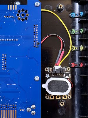
[[File:ZX-Spectrum-Next-Internal-Adafruit-Speaker-Amplifier.jpg|thumb|center|An Adafruit STEMMA Speaker with integrated amplifier connected to the Spectrum Next Issue 2B motherboard and held in place inside the case with self-adhesive velcro strips. Cable colors do not reflect GND and Vcc correctly, but the cable sleeves do.]] | |||
Solder GND to [[Circuit_Diagrams#J15_-_Next_GPIO|J15 pin 20]], Vcc to J15 pin 19, and the signal input to J3 pin 4 next to the speaker holes on the PCB. Attach the speaker board to the Next case using two pieces of self-adhesive velcro. Place it next to the PCB and near the ZX Spectrum Expansion Connector. See the photo above. | |||
Remove the Expansion Connector cover for better sound, and turn the potentiometer on the speaker board all the way up. | |||
The internal speaker can be disabled from the TBBlue boot ROM options menu. | The internal speaker can be disabled from the TBBlue boot ROM options menu. | ||
Revision as of 20:19, 30 August 2023
The Spectrum Next can create sound using Turbo Sound Next (3 AY-3-8912 sound chips) controlled by the BASIC PLAY keyword and the signal from these goes to the HDMI port or the 'ear' socket. Additionally an internal speaker can be connected which will generate sound in the same manner as the original 48k Spectrum, controlled via the BEEP keyword, which will also output via HDMI/ear.
A speaker attaches to connector J3 on the circuit board and requires a 2.54mm Pitch, 4 Way, 1 Row through-hole pin header. If you're fitting the board inside an original rubber key case, you'll probably need a right-angled connector due to the height required.
The buzzer should be approximately 1 inch diameter with impedance of 16 ohm (which should equate to a basic 'PC BIOS' piezo type speaker). J3 pins 1 and 2 are negative, pins 3 and 4 are positive.
On the Issue 2B boards, many users found the above speaker too quiet. For volume levels similar to the original ZX Spectrum, use an integrated amplifier/speaker board like the Adafruit STEMMA Speaker instead. A 3-pin JST PH 2.0 mm female header cable makes disconnecting it again easy.

Solder GND to J15 pin 20, Vcc to J15 pin 19, and the signal input to J3 pin 4 next to the speaker holes on the PCB. Attach the speaker board to the Next case using two pieces of self-adhesive velcro. Place it next to the PCB and near the ZX Spectrum Expansion Connector. See the photo above.
Remove the Expansion Connector cover for better sound, and turn the potentiometer on the speaker board all the way up.
The internal speaker can be disabled from the TBBlue boot ROM options menu.